
Secure wireless utility metering system for distant areas in Germany
About the Client

Company’s Request
Technology Set
Gateway | Raspberry Pi CM4, OpenWRT, C++, GRPC, MQTT, LoRaWAN, WMBus, Bash, Cron, Redis, PostgreSQL, ChirpStack, FTP, Linux |
Smart Reader | STM32WL series, WMBus, LoRaWAN, C |
Cloud and Web Platform | Django/Python, TimescaleDB, PostgreSQL, Redis, MQTT, Loki, Grafana, Nginx, React (frontend) |

The final product includes three main technical blocks. The first is the Smart Reader. The second is the Gateway (GW). The third is the cloud platform and the web portal. All three were developed and tested by our team.
The Smart Reader is a small device that is mounted close to a household electricity meter. It connects to the meter using one of several standard communication interfaces. The first option is infrared, which uses the SML optical port. This is very common in Germany. The second option is UART, and the third is RS. The latter are both wired serial connections. All of these interfaces are supported in our firmware. After connecting to the meter, the Smart Reader receives the measurement data. This data is in SML format and is not encrypted at this stage. The Smart Reader processes this raw data locally and immediately encrypts it using the WMBus protocol. Once encryption is complete, the Smart Reader sends the data to the Gateway using LoRaWAN. This means the Gateway does not need to perform any encryption or decryption operations. It only forwards the already-encrypted packet directly to utility company device.
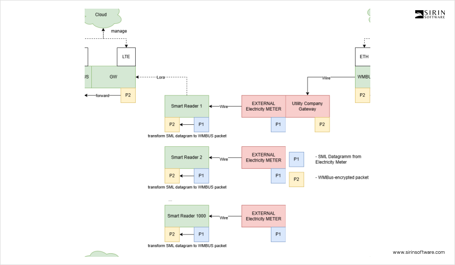
We selected the STM32WL-series microcontroller as the base for the Smart Reader hardware. This chip was a good choice because it combines an ARM Cortex-M core with an integrated LoRa radio module. We built the full electronics design ourselves. We also wrote the firmware in C from scratch. The Smart Reader is enclosed in a custom case that fits on a DIN rail. This is the standard mounting method inside electrical cabinets in Europe.
Designing the enclosure was also our task. One of the most difficult parts during development was building a proper antenna for long-range LoRa communication.
We had to tune the antenna to support communication up to 15 kilometers in rural areas. At the same time, the size of the device was limited by the DIN rail format. To solve this, our team tested and adjusted multiple antenna versions until we reached stable performance over the required distance.
Another major challenge was the physical layout of components inside the enclosure.
Because the case had to combine a high-voltage power section with the sensitive RF part, we had to prevent electrical noise from interfering with the antenna. Our engineers carefully planned the internal structure. They placed the RF board and high-voltage components at a 90-degree angle to each other, kept all RF parts on one side of the board, added a full ground layer on the back of the RF PCB, and physically separated the boards using a custom connector. This design helped eliminate signal interference and allowed the antenna to work with stable performance even in compact housing.
The Smart Reader firmware had several key challenges. One of them was related to time. In Germany, the external metering gateways that receive data expect to get it in very precise time windows. For example, if the Smart Reader sends a packet at 12:00, the next packet must arrive exactly at 12:15. Not earlier, not later, and for the whole lifespan of a reader. If a packet arrives outside this window, even by a few seconds, it is rejected. That is why we had to make sure that each Smart Reader keeps precise internal time. We also had to implement synchronization between the SR and the GW. Besides timing, there was another strict requirement. The delay between reading the data and delivering the encrypted packet to the utility gateway must not be longer than four seconds. This was especially hard to meet in bad radio conditions, but we succeeded by optimizing both internal logic and radio behavior.
The Gateway is the second main device in this system. Its main job is to collect encrypted packets from all nearby Smart Readers and forward them to the government-certified metering gateway. The Gateway does not decrypt the data. It acts only as a secure forwarder. To do this, it uses a hardware WMBus module. The packet is first delivered via UART inside the Gateway to this module, which then transmits the data over the wireless WMBus protocol. This last step completes the communication chain, and from there, the data goes to the utility infrastructure.
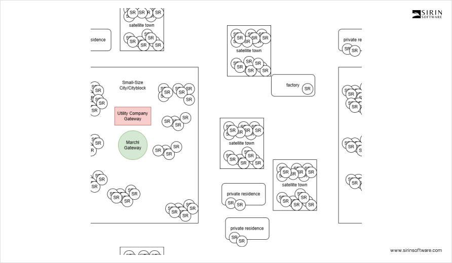
We used the Raspberry Pi Compute Module 4 as the base platform for the Gateway. We built a custom carrier board to allow modular expansion. This includes pluggable LoRa modules, LTE modems, and other components depending on deployment needs.
All components are designed to fit into DIN rail slots. On the software side, we installed OpenWRT as the main operating system. We added several services on top of it, including MQTT, GRPC, Bash scripting, Cron jobs, Redis, and PostgreSQL. We also integrated ChirpStack to manage the LoRaWAN communication.
One of the early design decisions was to run ChirpStack directly on the Gateway instead of in the cloud. This helped avoid performance problems and allowed us to scale easily. It also made it possible for each Gateway to operate in standalone mode when deployed in remote areas with poor Ethernet or LTE connection quality. If the internet connection is lost, the system keeps working locally without interruption. Since each Gateway may support up to 1,500 Smart Readers, traffic load and reliability were key concerns. To manage this, we wrote custom logic for traffic orchestration. This included scheduling, queuing, and retransmission strategies. Without this, the Gateway would not be able to keep up with thousands of messages per hour.
We also built logic to handle OTA firmware updates for the Smart Readers. This was a difficult task. LoRa is a narrowband protocol with strict duty cycle limits. It is not designed for sending large files. Updating over 1,000 devices using unicast would take many days. To fix this, we created a group-based OTA method. The Gateway sends update packets using multicast. Each Smart Reader in the group confirms the received chunks. If a device misses too many packets, it is removed from the group and updated separately. This helped reduce update times and improved reliability under poor radio conditions.

The cloud platform and web portal were developed entirely by our team. The backend is built in Django and Python. It uses PostgreSQL as the database, with TimescaleDB extension to support time-based data. For message exchange, we use MQTT. Monitoring is handled by Loki and Grafana. The frontend was built with React. Through this platform, operators can configure devices, trigger updates, assign settings, and monitor status. The cloud system also stores anonymized public metering data and generates detailed reports. In addition, it collects connection parameters from each device, such as signal-to-noise ratio, RSSI, and data rate. This information helps engineers identify and fix problems in installations with weak or unstable communication.
To test all parts of the system, we developed a QA harness. It is written in Python and runs inside Docker. It runs functional tests continuously and also acts as an observer. It continuously analyzes system behavior and raises warnings when it detects any abnormal operation. The harness communicates with real hardware located in our lab. All devices are connected to controllable power and are wired to real meters or simulators. For simulation, we built custom tools using Raspberry Pi that generate a stream of metering data. This allows us to test Smart Readers in realistic conditions even without physical meters. The harness runs API tests, connection checks, OTA update tests, and performance tracking. We also used this tool to detect packet loss, response delays, and configuration problems. The same tool also allowed us to prepare performance reports and system health dashboards, which were shared with the client and other stakeholders.
In addition to raw test data, we created visual charts. These showed packet delivery rates, latency over time, device uptime, and average performance by firmware version. These visuals helped us detect outliers and improve both Smart Reader firmware and Gateway behavior. In most tests, we reached the goal of delivering metering data within ten-minute intervals, which matches the standard check-in time of our LoRa devices. Around 75 percent of packets were delivered within this timing window. This number varies depending on signal conditions, with lower delivery rates around 50 percent at -120 dBm RSSI and up to 95 percent in strong signal areas. Improving this success rate is an active task for our team as part of ongoing system optimization.
During the full project, we went through four major development stages. First, we built a feasibility prototype that included the Gateway and the cloud. After that, we produced the first real Gateway hardware. Then, we built and integrated the Smart Reader into the system. In the last phase, we started field testing. Our team deployed around 150 SR devices in nearby localities, in cooperation with a real utility company. The devices were placed in diverse environments, with most located within 500 meters of the Gateway, and some installed at longer distances of several kilometers. These included locations with complex terrain and building layouts, allowing us to test the system in realistic and challenging conditions.. These tests allowed us to check real-world signal coverage, timing accuracy, and error rates. We also used the results to plan the final certification steps.
Throughout this work, we had to deal with many limitations. Most were related to timing, encryption, and bandwidth. To meet them, we had to read and understand many parts of the OMS specification. OMS stands for Open Metering System. It is a European standard used in energy infrastructure. We reviewed technical documentation in German and mapped its requirements to our firmware and hardware designs. Even though our system is not yet certified, it is built to comply with all main OMS requirements where possible. Our team continues to track OMS updates and align our work with it.

In parallel, we always kept future production in mind. Our designs are modular. Firmware updates are easy to apply. Hardware components are swappable and can be reused. All this allows the client to scale the product without deep changes to the system.
Right now, we have a complete solution. The Smart Readers work. The Gateways are stable. The cloud platform is ready. We are entering the final field testing phase. Mass production has not yet started, but from a technical point of view, the system is ready. The next important step will be preparing for scaled manufacturing. This will include setting up automated production processes, where each device is flashed, provisioned with certificates, registered in the system, runs self-tests, and then moves to shipment. We are planning this together with the client and production partners to ensure a reliable rollout.
*This logo is used to indicate that this solution is built on STMicroelectronics technology. This does not imply a formal partnership or endorsement by STMicroelectronics.
Value Delivered
